gtrace Tutorial
This Jupyter notebook walks you through how to use the gtrace package.
Import modules
First, we import related modules
[1]:
import gtrace.beam as beam  # Gaussian beam module
import gtrace.optcomp as opt  # Optical components
import gtrace.draw as draw  # A module to draw results into CAD files
from gtrace.draw.tools import drawAllBeams, drawAllOptics, transAll, rotateAll #Utility functions for drawing
import gtrace.draw.renderer as renderer
from gtrace.unit import *  # A convenience module to represent various modules
import gtrace.optics.gaussian as gauss # A utility module for Gaussian beams
from gtrace.nonsequential import non_seq_trace #Non-sequential trace
from gtrace.optics.geometric import vector_normalize #A function to normalize a vector

import numpy as np  #Numpy
pi = np.pi  #Just for brevity
Coordinates and directions
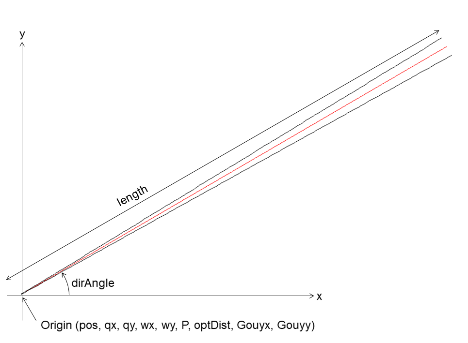
In gtrace, everything is put on a 2D plane and we use a Cartesian coordinate system with x- and y-axis.
Sometimes, you may want to specify a direction in the 2D space, such as a beam propagation direction or the direction of a mirror surface representated by its normal vector. You can use either a unit vector or an angle to specify a direction. When using an angle, it is always measured from the X-axis in counter-clockwise. Therefore, a unit vector having a direction angle \(\theta\) has components \((\cos\theta, \sin\theta)\).
Gaussian beam object
A Gaussian beam object:
[2]:
#q-parameter of the beam
q0 = gauss.Rw2q(ROC=np.inf, w=0.3*mm)

#Create a GaussianBeam object.
b0 = beam.GaussianBeam(q0=q0, wl=1064*nm, length=30*cm, P=1.0)

#Set the direction angle of the beam to 10deg from the global x-axis.
b0.dirAngle = deg2rad(10)

#Set the position of the origin of the beam
b0.pos = (0.0, 0.0)
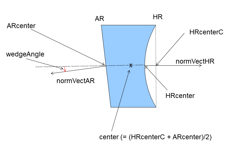
Define mirrors
Mirror object:
[5]:
M1 = opt.Mirror(HRcenter=[50*cm, 10*cm], normAngleHR=pi,
                 diameter=25*cm, thickness=10*cm,
                 wedgeAngle=deg2rad(0.25), inv_ROC_HR=1./(120*cm),
                 inv_ROC_AR=0,
                 Refl_HR=0.9, Trans_HR=1-0.9,
                 Refl_AR=500*ppm, Trans_AR=1-500*ppm,
                 n=1.45, name='M1')

M2 = opt.Mirror(HRcenter=[0*cm, 18*cm], normAngleHR=deg2rad(5.0),
                 diameter=15*cm, thickness=5*cm,
                 wedgeAngle=deg2rad(0.25), inv_ROC_HR=-1./(350*cm),
                 inv_ROC_AR=0,
                 Refl_HR=0.9, Trans_HR=1-0.9,
                 Refl_AR=500*ppm, Trans_AR=1-500*ppm,
                 n=1.45, name='M2')

M3 = opt.Mirror(HRcenter=[30*cm, 30*cm], normAngleHR=deg2rad(21.3),
                 diameter=15*cm, thickness=5*cm,
                 wedgeAngle=deg2rad(1), inv_ROC_HR=1./(350*cm),
                 inv_ROC_AR=0,
                 Refl_HR=0.9, Trans_HR=1-0.9,
                 Refl_AR=500*ppm, Trans_AR=1-500*ppm,
                 n=1.45, name='M3')
Sequential beam trace
Prepare a dictionary to save beams
[6]:
beamDict = {}
Hit the mirror M1 with the beam b1 from the HR side
[7]:
beams = M1.hitFromHR(b0, order=2)
Returned object (beams) is a dictionary containing the resulting beams. The names of the beams are the following.
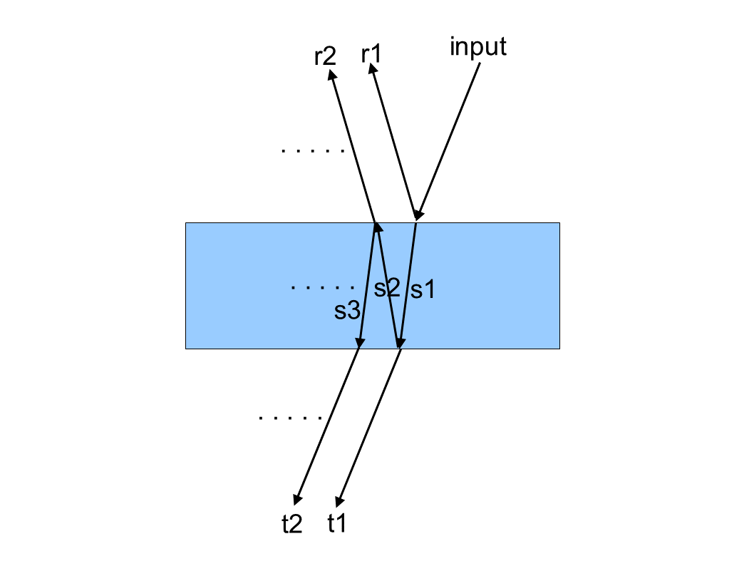
Trace the remaining beam path
[9]:
#Save the incident beam to the beam dictionary
beamDict['input_beam'] = beams['input']

#Save other beams
beamDict['M1s1'] = beams['s1']
beamDict['M1t1'] = beams['t1']
beamDict['M1s2'] = beams['s2']
beamDict['M1s3'] = beams['s3']
beamDict['M1t2'] = beams['t2']

#Reflected beam from M1
b = beams['r1']

#Hit M2
beams = M2.hitFromHR(b, order=2)

#Save the beam from M1 to M2
beamDict['M1toM2'] = beams['input']
beamDict['M2s1'] = beams['s1']
beamDict['M2t1'] = beams['t1']

#Reflected beam from M2
b = beams['r1']

#Hit M3 from AR
beams = M3.hitFromAR(b, order=2)

#Save beams
beamDict['M2toM3'] = beams['input']
beamDict['M3s1'] = beams['s1']
beamDict['M3t1'] = beams['t1']
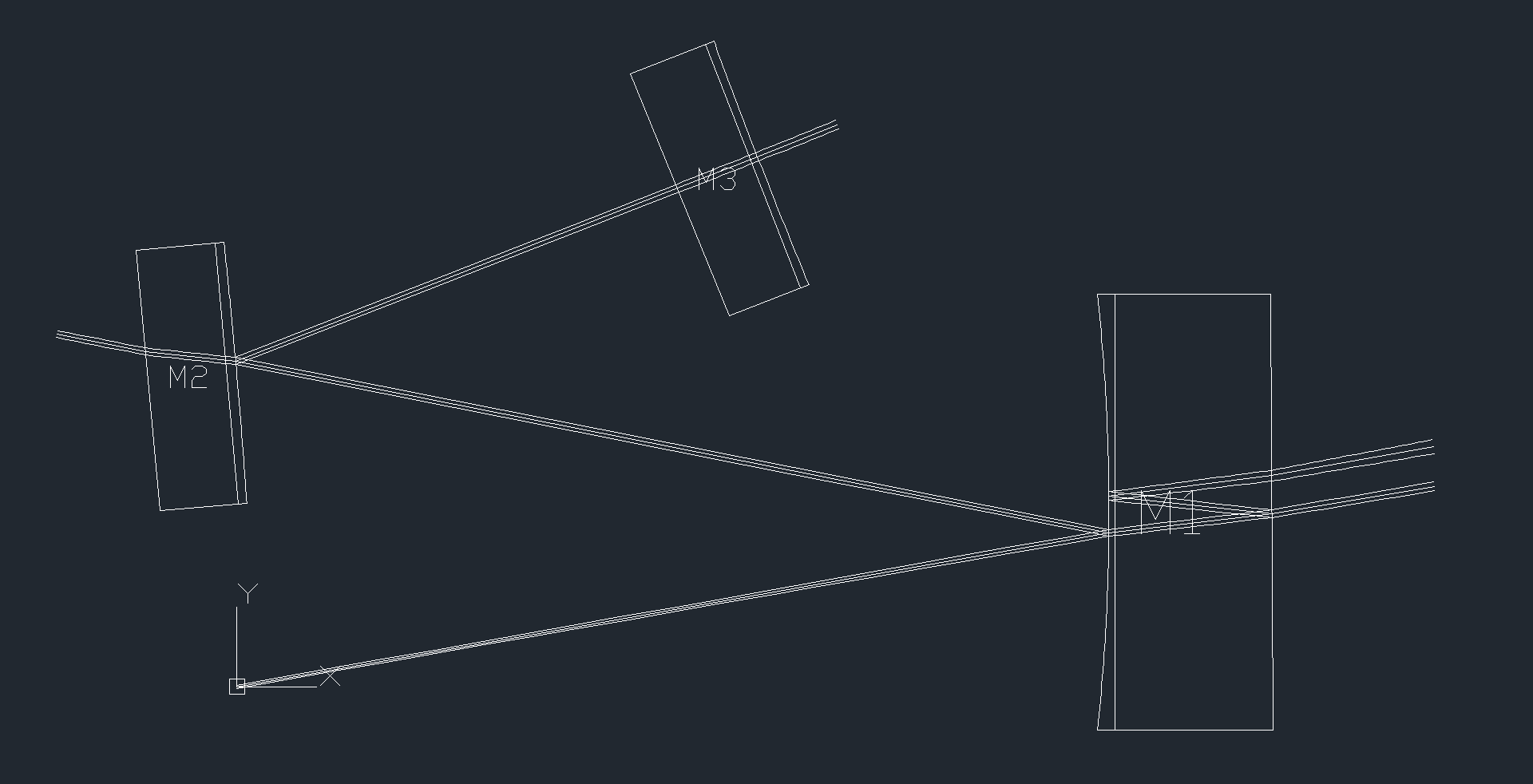
Draw the results
[10]:
#Create a canvas object
cnv = draw.Canvas()

#Add a layer to the canvas
cnv.add_layer("main_beam", color=(0,0,0))

#Draw all the beams in beamDict
drawAllBeams(cnv, list(beamDict.values()), drawWidth=True, sigma=3.0, drawPower=False,
                 drawROC=False, drawGouy=False, drawOptDist=False, layer='main_beam',
                    fontSize=0.01)

#Draw the mirror
drawAllOptics(cnv, [M1,M2,M3])

#Save the result as a DXF file
renderer.renderDXF(cnv, 'SeqTrace.dxf')
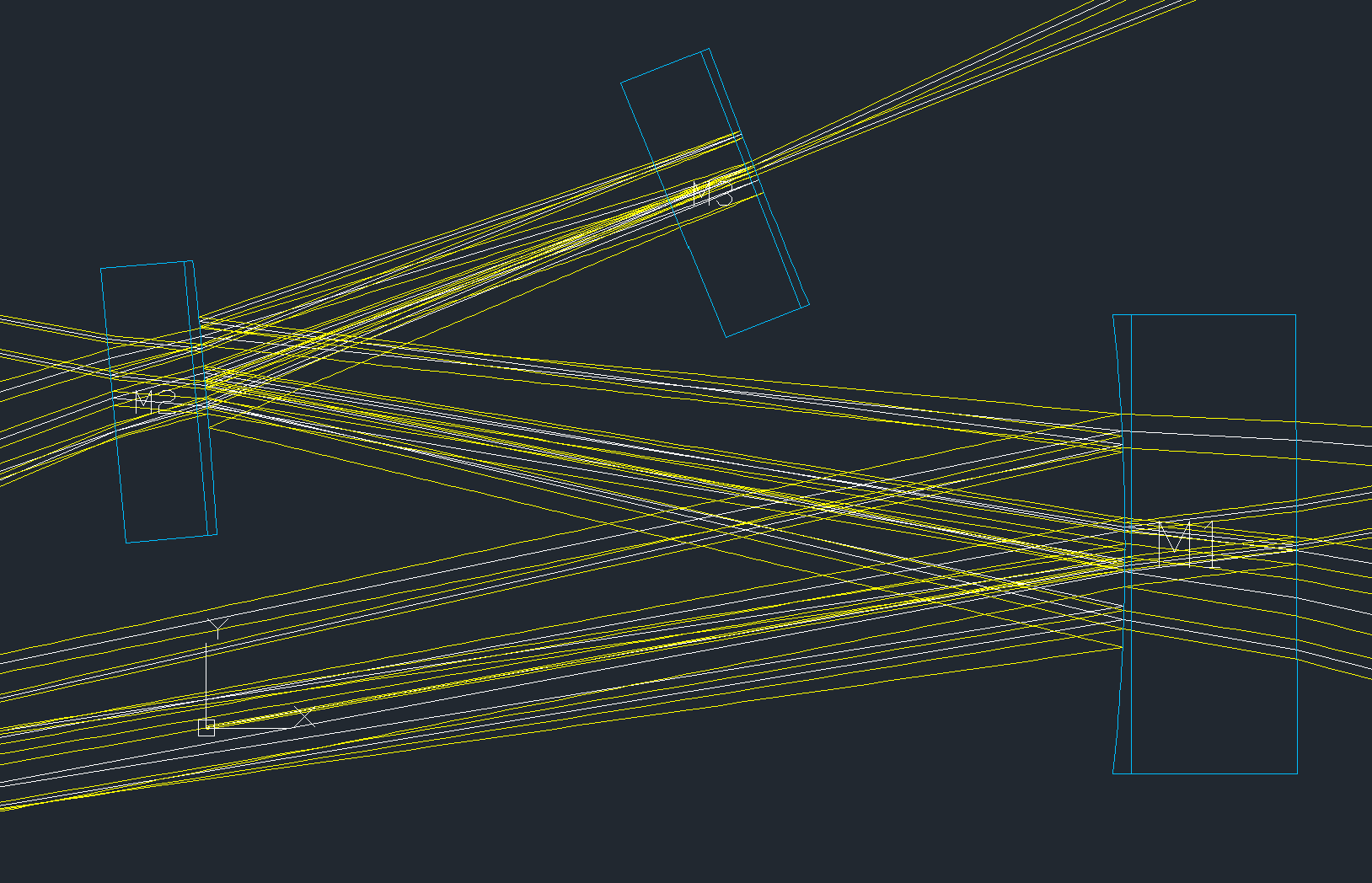
The generated DXF file looks like this.
Non-sequential trace
In the above example, we instructed which beam should hit which optic explicitly. Here, we only specify an input beam and a set of optics. Then let the beam go around until specfied criteria are met. This is called “Non-Sequential Trace”.
Perform non-sequential trace
[11]:
# Trace beams until the power is less than 1e-6 or 30th order internal reflections
beams = non_seq_trace([M1,M2,M3], b0, order=30, power_threshold=1e-6)
Draw results
[13]:
#Create a canvas object
cnv = draw.Canvas()

#Add a layer to the canvas
cnv.add_layer("main_beam", color=(0,0,0))

#Draw all beams

drawAllBeams(cnv, beams, drawWidth=True, sigma=3.0, drawPower=False,
                 drawROC=False, drawGouy=False, drawOptDist=False, layer='main_beam',
                    fontSize=0.01)

#Draw the mirror
drawAllOptics(cnv, [M1,M2,M3])

#Save the result as a DXF file
renderer.renderDXF(cnv, 'NonSeq.dxf')
[49]:
a=cnv.layers['main_beam']
[52]:
b=a.shapes[0]
[54]:
b.stop
[54]:
(0.4999415205870579, 0.0881531788559148)
The generated DXF file looks like this.
KAGRA Input Mode Cleaner
Parameters
[14]:
nsilica = 1.44967

MC_Dia = 10.0*cm
MC_Thick = 3.0*cm
MCe_ROC = 37.3

MCi_Refl = 0.9937
MCo_Refl = 0.9937
MCe_Refl = 0.9999
AR_Refl = 0.1/100

pos_MCi = np.array([-0.25, 0.0])
pos_MCo = np.array([0.25, 0.0])
pos_MCe = np.array([0, 2.63986994e+01])
Define MC mirrors
[15]:
MCi = opt.Mirror(HRcenter=[0,0], normAngleHR=0.0,
                 diameter=MC_Dia, thickness=MC_Thick,
                 wedgeAngle=-deg2rad(2.5), inv_ROC_HR=0.0,
                 Refl_HR=MCi_Refl, Trans_HR=1-MCi_Refl,
                 Refl_AR=AR_Refl, Trans_AR=1-AR_Refl,
                 n=nsilica, name='MCi')

MCo = opt.Mirror(HRcenter=[0,0], normAngleHR=0.0,
                 diameter=MC_Dia, thickness=MC_Thick,
                 wedgeAngle=deg2rad(2.5), inv_ROC_HR=0.0,
                 Refl_HR=MCo_Refl, Trans_HR=1-MCo_Refl,
                 Refl_AR=AR_Refl, Trans_AR=1-AR_Refl,
                 n=nsilica, name='MCo')

MCe = opt.Mirror(HRcenter=[0,0], normAngleHR=0.0,
                 diameter=MC_Dia, thickness=MC_Thick,
                 wedgeAngle=deg2rad(2.5), inv_ROC_HR=1.0/MCe_ROC,
                 Refl_HR=MCe_Refl, Trans_HR=1-MCe_Refl,
                 Refl_AR=AR_Refl, Trans_AR=1-AR_Refl,
                 n=nsilica, name='MCe')
Put MC mirrors
[16]:
#Put mirrors in position
MCi.HRcenter = pos_MCi
MCo.HRcenter = pos_MCo
MCe.HRcenter = pos_MCe

#Align the mirrors to form a triangular cavity
v1 = vector_normalize(pos_MCi - pos_MCo)
v2 = vector_normalize(pos_MCe - pos_MCo)
MCo.normVectHR = (v1+v2)/2

v2 = vector_normalize(pos_MCe - pos_MCi)
MCi.normVectHR = (-v1+v2)/2

MCe.normVectHR = np.array([0.0, -1.0])
MC eigen mode
Now we compute the eigen mode of the MC by tracing a beam round trip of the MC then extracting the ABCD matrix
[17]:
#Test beam (beam parameters does not matter)
b = beam.GaussianBeam(q0=gauss.Rw2q(ROC=np.inf, w=1*mm), wl=1064*nm)

#Put the beam on the surface of MCi
b.pos = MCi.HRcenter

#Direct the beam to the center of MCo
b.dirVect = MCo.HRcenter - b.pos

#Hit MCo
beams = MCo.hitFromHR(b)
b = beams['r1']

#Hit MCe
beams = MCe.hitFromHR(b)
b = beams['r1']

#Hit MCi
beams = MCi.hitFromHR(b)
b = beams['r1']

#Extract the round trip ABCD matrix in the horizontal direction
A = b.Mx[0,0]
B = b.Mx[0,1]
C = b.Mx[1,0]
D = b.Mx[1,1]
#q-parameter of the MC eigenmode beam
qxMC = 1.0/((D-A)/(2*B)-1j*np.sqrt(4-(A+D)**2)/(2*B))

#Extract the round trip ABCD matrix in the vertical direction
A = b.My[0,0]
B = b.My[0,1]
C = b.My[1,0]
D = b.My[1,1]
#q-parameter of the MC eigenmode beam
qyMC = 1.0/((D-A)/(2*B)-1j*np.sqrt(4-(A+D)**2)/(2*B))

#Update the q-parameter of b
b.qx = qxMC
b.qy = qyMC

#Name it bMC
bMC = b.copy()
Waist size and position of the MC eigenmode (measured from the MCi HR surface)
[18]:
bMC.waist()
[18]:
{'Waist Size': (0.002388588001545699, 0.002388775565011432),
 'Waist Position': (0.25000000000000416, 0.25000000000000505)}
Trace the beam in the MC again
[19]:
beamDict = {}

#Hit MCo
beams = MCo.hitFromHR(b, order=1)
beamDict['MCitoMCo'] = beams['input']
beamDict['MCos1'] = beams['s1']
beamDict['MCot1'] = beams['t1']

b = beams['r1']

#Hit MCe
beams = MCe.hitFromHR(b, order=1)
beamDict['MCotoMCe'] = beams['input']
beamDict['MCes1'] = beams['s1']
beamDict['MCet1'] = beams['t1']

b = beams['r1']

#Hit MCi
beams = MCi.hitFromHR(b, order=1)
beamDict['MCetoMCi'] = beams['input']
beamDict['MCis1'] = beams['s1']
beamDict['MCit1'] = beams['t1']
Draw MC beams
[20]:
#Create a canvas object
cnv = draw.Canvas()

#Add a layer to the canvas
cnv.add_layer("main_beam", color=(0,0,0))

#Draw all beams

drawAllBeams(cnv, list(beamDict.values()), drawWidth=True, sigma=3.0, drawPower=False,
                 drawROC=False, drawGouy=False, drawOptDist=False, layer='main_beam',
                    fontSize=0.01)

#Draw the mirror
drawAllOptics(cnv, [MCi,MCo,MCe])

#Save the result as a DXF file
renderer.renderDXF(cnv, 'MC.dxf')
The generated DXF file looks like this:
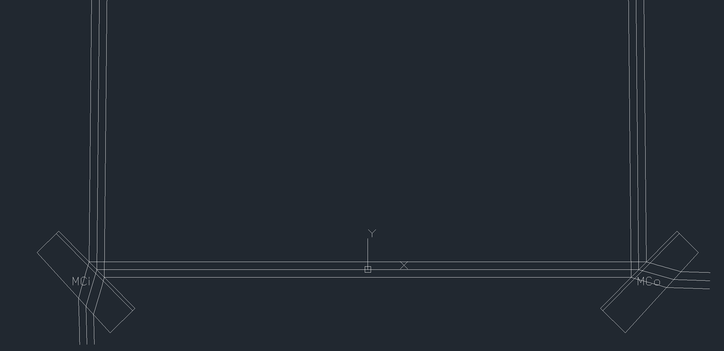
[ ]: